CPUs and Robot Brains
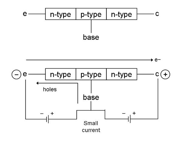
Above: a circuit diagram of a transistor (of the npn type). Normally
no current will flow between the collector (c) and the emitter (e)
unless a small current is applied to the base, opening the gate and
allowing the main current to pass from c to e (electron flow from e to
c).
The necessary voltage for the base to allow the passage of the main
current from c to e is about 0.7V. So transistors are like electronic
switches that can turn the current On and Off. We can easily turn on the
transistor because the base-to-emitter part of a transistor works like a
diode, which has a forward voltage that it “grabs” from the available
voltage. In order to get 0.7V, we need to add a resistor to this, so
that the rest of the voltage drops across the resistor. So this is
basically how a transistor works, but there are different
types of transistors. Transistors are usually integrated into circuits,
they are like billions of miniature cells for computers.
Robots need advanced computer systems to carry out the vast array of
computations needed to make a robot perform useful work and conduct
itself in a responsible and sensible way. Processing signals from
thousands of sensors and controlling the fine movements of dozens of
actuators in real time is a demanding job, and that's without the higher
processing needed, say, to hold a meaningful conversation about
philosophy, which is sufficiently adept to have the potential to
generate novel ideas!
The principle type of processor currently in use on Earth is the silicon
chip - a solid-state semi-conductor based CPU in which circuits have
been etched or deposited in nanometre detail on a crystal of silicon.
The elementary component of these circuits is the transistor.
Transistors have three connection points or 'leads'. One of these, the
base, is used to control the flow of current between the other two: from
the collector, c, to the emitter, e, remembering that electric current
is defined to be positive by definition and so opposite to the flow of
electrons. In this way a transistor basically functions as an electronic
valve controlling the flow of charge: a small current applied to
the base will open the gate and allow a much larger current to flow from
c to e. (See Electro Fogey's practical electronics lectures on Youtube
for an excellent explanation of how transistors work: What
is a transistor?)
Binary
logic
Silicon-based
computers operate using binary logic - a signal in a circuit either
flows above a certain threshold or it doesn't. We indicate this using
binary digits or bits. A bit can have only one of two possible values:
1 if current flows (ON) and 0 if it does not (OFF). See binary operations for examples of how
computing makes use of binary logic.
How
do transistors make intelligent circuits?
Computers,
and robot brains, operating in binary require several elementary
operations, which as we shall see allow more complex computations to
take place. These elementary circuits are: NOT, AND, OR and XOR gates.
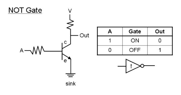
The
NOT gate simply inverts its input, which consists of a binary signal
represented by 1 if current flows, 0 if current does not flow. If
current flows into the base of the transistor, from A, then the gate
between c and e is open and current will be diverted to flow from c
to e (driven by voltage source V) reducing current flow to the
output (depending on the resistance in the 'out' circuit, with a
resistance much higher than the transistor current flow to out will
be small). (In this case this current is simply drained away to
earth by a 'sink'). This is output 0. If, however, no current flows
into A then the gate will not open and all the current will flow to
out, giving an output of 1. In other words, when the input is high
the output is low, and when the input is low the output is high. The
NOT gate is a signal inverter.
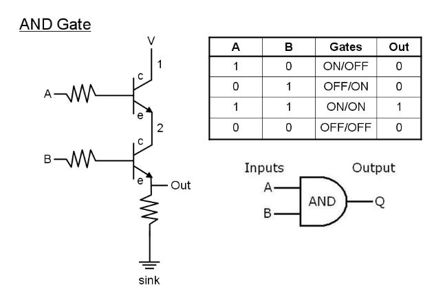
An AND gate requires two inputs, A and B, and two transistors gated by these inputs. In this case, current will flow from V to Out if both gates are open, that is when a current flows in BOTH a AND B.
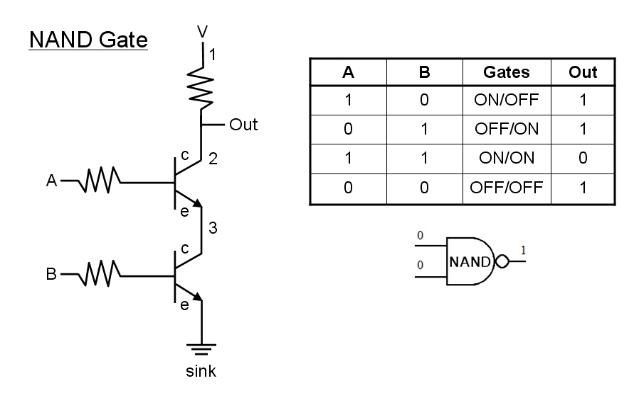
A NAND gate is a 'NOT AND' gate and is the logical representation of an AND gate followed by a NOT gate and its output is the inverse of an AND gate. In this case, high current will only flow to OUT when either gate A and/or gate B is closed, that is when there is input in neither A nor B or no input in both A and B.
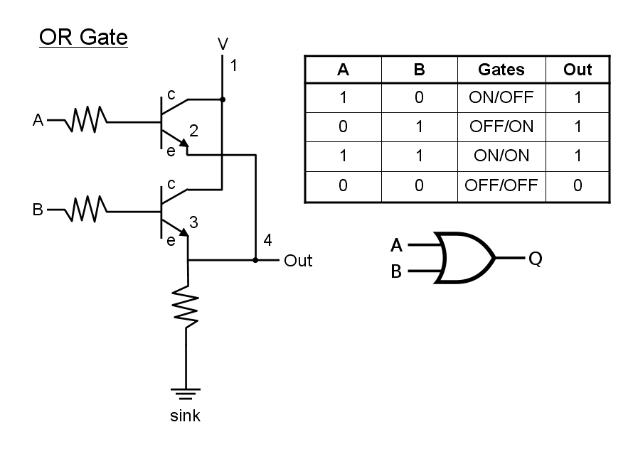
An OR gate will send a high signal to Out if there is an input in either A OR B or in both A and B. This is an inclusive OR, since it includes the situation when BOTH A and B = 1 (i.e. have input currents).
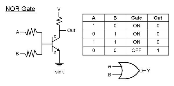
A NOR gate is the logical combination of an OR gate followed by a NOT gate and has the inverted output of an OR gate. Input from either A OR B, or inputs from both A AND B will divert current away from out to the sink.
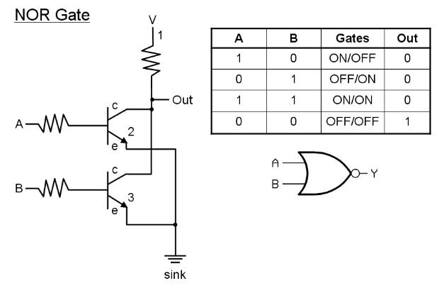
Above: an alternative NOR gate utilizing two transistors.
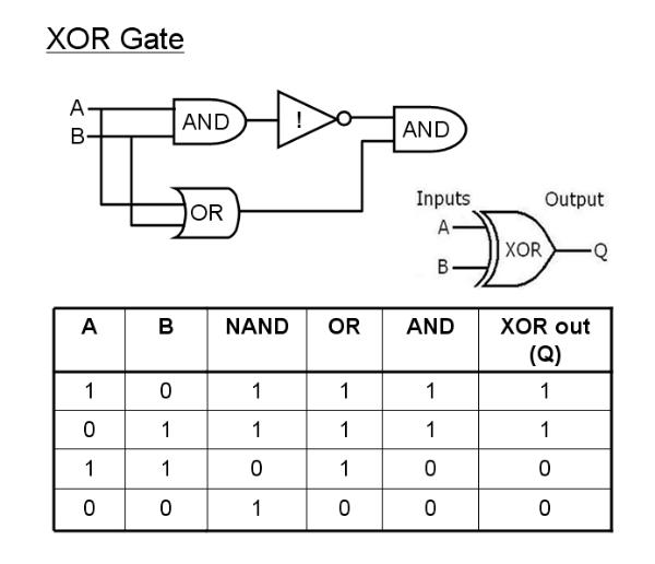
The XOR gate is an alternative type of OR gate which excludes the possibility of both inputs = 1. In other words, the output is 1 if input A OR input B = 1 but not if A = B = 1.
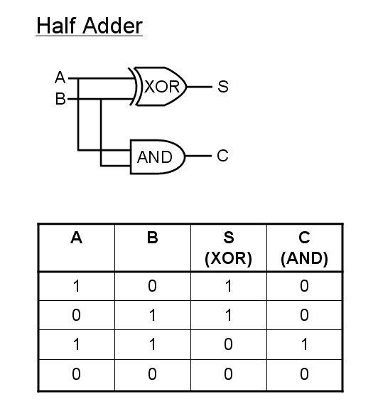
The
half-adder circuit will add two bits as follows:
0 + 0 = 0
1 + 0 = 1
0 + 1 = 1
1 + 1 = 0 carry 1
If A=B=1 then the circuit overflows as we need a more significant
bit. (E.g. in binary 1 = 2 in decimal, so 1 + 1 = 1 + 1 in decimal =
2 = 10 in binary). The carry bit, C, carries 1 over to any
subsequent computations, so for a full adder we need an additional
input for a carry bit:
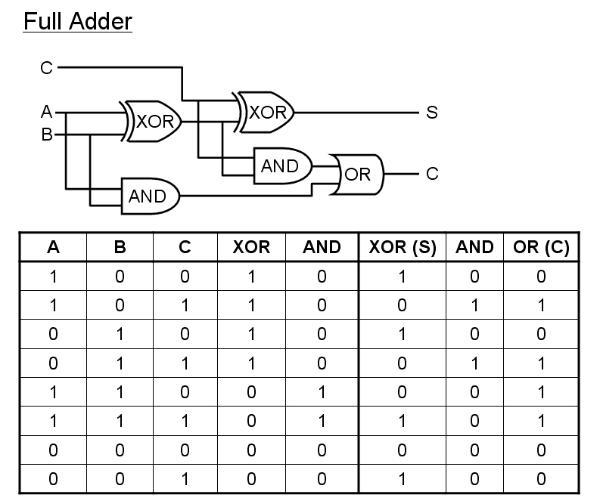
In
the full adder, A and B represent the bits being added and input C
represents the carry bit coming into the computation, which will be
zero unless a carry is left over from a previous computation. The
first XOR and AND gates operate on inputs A and B; The second XOR
operates on C and the output of the first XOR to determine the
result of the addition (e.g. 1 + 0 with no carry = 1) whilst the
second AND and the second OR gates determine whether or not a carry
remains. E.g. A = 1 + B = 1 + C = 0 gives S = 0, C = 1; whilst: A =
1 + B = 1 + C =1 gives S = 1 and C = 1.
With binary addition we can also carry out other elementary binary
manipulations, such as subtraction, multiplication and division. For
example, to multiply a number by 3, we simply add that number to
itself twice.
For
more details see - 'Thinking
like a Computer' - binary arithmetic
Quantum
Processors
Silicon
chip design has achieved a remarkable degree of development by
miniaturising the transistor circuits, which also means that they
can compute more rapidly and with a lower power consumption.
However, there comes a point when the walls between adjacent charge
pathways or channels ('wires') is so small (on a near atomic scale)
that charge randomly leaks from one channel to the next by quantum
tunneling (that is the electron simply jumps or teleports from one
channel to a neighbouring channel).
Of course, we can compensate by making silicon chips larger, or by
having multi-core
processors
consisting of several silicon chip CPUs (central processing units).
This does complicate software development considerably, however, and
programming techniques to optimise the use of multicore processors
are still being developed and are still catching on due to the
necessary learning curve for software developers. Adding in 8
processors instead of 4 does not simply double computation power in
of itself! Rather, the software must be able to make optimum use of
the extra processor cores by efficiently dividing work among them.
This gives rise to true parallel
processing
in which more than one task can be computed side-by-side in real
time. Processors with single cores can emulate parallel processing
when more than one program is running by rapidly jumping from one
program to another, but actually only one of the programs is ever
being executed at any instant of time. This is the basis of multi-threading, in which each thread
represents one line of code execution and the CPU rapidly jumps
between threads.
Other ways to enhance computational power may be to use DNA
computers or quantum computers, which are able to perform
calculations in parallel even on a single core. A quantum computer
uses qubits rather than bits. A qubit
(quantum bit)
can have the value of 1 or 0, just like a bit, but it can also have
the value of 0 and 1 simultaneously (or neither value depending how
you look at it)!
A qubit can be represented physically by a spin-half particle, such
as a silver atom or an electron, which can have either spin-up (= 1
say) or spin-down (= 0). However, quantum superposition allows the particle to be
in a combined coherent
state
where it is both spin-up and spin-down until we actually measure the
direction of its spin in which case it's state will collapse and
then it will be either spin-up or spin-down (a strong measurement,
see quantum measurement). This kind of superposition is possible
since particles like atoms are also waves and waves can be
superimposed (added on top of one-another) to generate a new wave.
In principle this enables faster parallel computations since we now
have more than just two possible states for each bit whilst
calculations are underway, though the final result is still binary:
spin-up or spin-down.
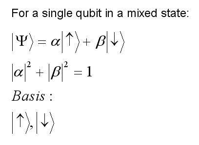
The state of our particle is given by a wavefunction, represented by
the Greek letter psi which is a mixture of up and down spins. For
example, we might have twice as much up character as down character.
Since the square of the wavefunction gives us the probability of
finding the particle in a spin-up state or a spin-down state
following a measurement, and the sum of the probabilities must equal
1, we have:
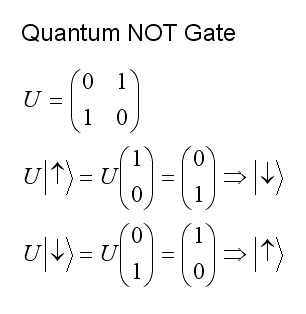
The basis represents the possible pure states, spin-up and spin-down in this case. A quantum NOT gate must invert the spins: converting spin-up character into spin-down character and vice-versa. Certain measurements or operations carried out on the particle can achieve this state inversion. In quantum mechanics spin states are represented by vectors and operations (measurements) by matrices. For example, a quantum NOT gate can be represented by the matrix U operating on a spin state by multiplying it to give a new spin state thus:
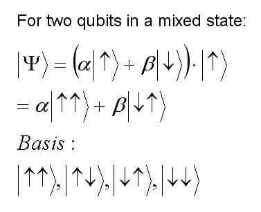
Things get more interesting when we have two qubits. The two wavefunctions, one for each qubit, will be coherent and entangled, that is connected if they overlap significantly (an example of superposition of waves again). Thus, they behave like a single mixed state:
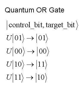
Since the two qubits are entangled, we can change one intentionally, called the control qubit, and the other, the target qubit, will change in some determined way as a result of a computation. For example, in a quantum OR gate, the second qubit can be flipped (inverted) if the first qubit = 1 and left unchanged otherwise.
One
potential problem with quantum systems is that entanglement and
coherence is that they tend to be short-lived since thermal
fluctuations (thermal noise) can collapse the system and change the
values of the qubits unpredictably. This can be minimised by cooling
the quantum computer to very low temperatures, or by stabilising
molecules in the vicinity to prevent thermal collisions.
Interestingly, the latter appears to occur in living cells and has
led to speculation that living cells may be quantum computers. What
is essential is some form of error checking and error correction.
We can of course measure the spin directions, but we wish to do so
in some way which does not cause the system to collapse into a
definite spin-up or spin-down state (we want to preserve the
coefficients alpha and beta which indicate the proportions of
'upness' and 'downness'). we can do this by using three qubits to
represent a spin state:
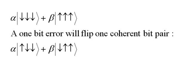
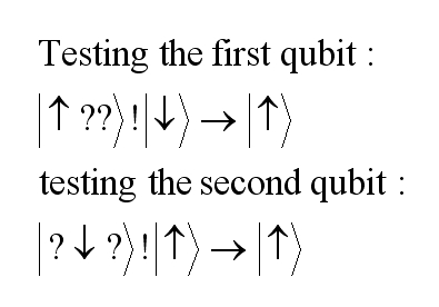
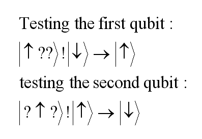
A collective measurement on the first two qubits can determine whether or not they are pointing in the same direction, without perturbing the system by measuring each individual system (maintaining the entanglement). If the directions of the first two qubits differ then an error has occurred. We can then similarly compare the last two spins. We can do each pair-comparison using two successive NOT (!) gates using an addition 'maid' qubit to help with the calculation. In this operation we flip (NOT, !) the maid qubit if the comparative qubit in our triple is pointing upwards and leave it unchanged otherwise. If an error has occurred and the two spins differ then the maid qubit will be flipped once as follows:
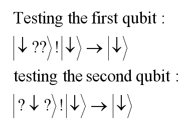
If the two qubits being tested are aligned then the maid qubit gets flipped either twice or not at all, and so remains unchanged:
Having a powerful computational mind is one thing, but would our robot with its multi-quantum core processor ever be conscious? Could we ever know? Before we even attempt to answer such a question, we need to define what consciousness is, if we can.
Modeling Logic Gates with Matrices
As an interesting aside, which can also be an aid to computation of logic circuits, let us see how we can model logic gates as matrices.
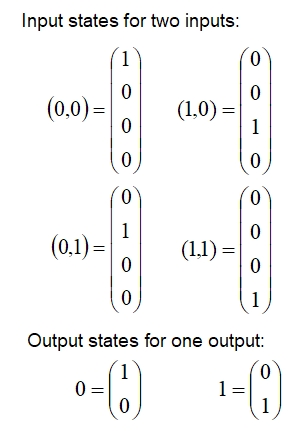
First let us adopt a
system of matrices to represent 2 bit inputs and a one-bit output as
matrices as follows:
Next we need a matrix representation of the operators, each operator acting as a logic gate to process a pair of input bits into an output bit. One such choice of matrices is as follows:

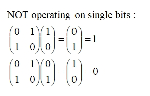
The rule is that every column of each matrix contains a pair of opposite values (0, 1) or (1, 0). Note the NOT gate acts on a single bit to invert it as follows:
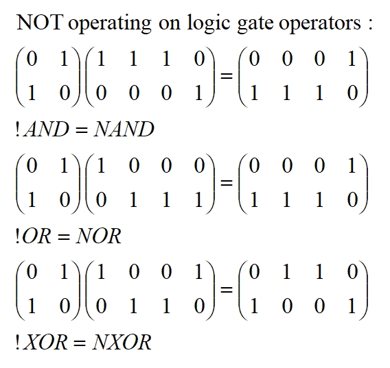
NOT operating on the standard log-gate operators:
For example,the AND gate would operate as follows (making use of standard matrix multiplication):
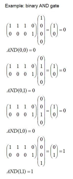
If you are comfortable with matrix multiplication then why not try the NAND gate and one or two others? You might like to use the free online tool Symbolab: https://www.symbolab.com
Modeling Neural Circuits with Matrices
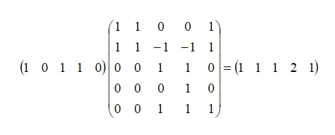
It is possible to model neural circuits using matrices. For example consider the circuit below:
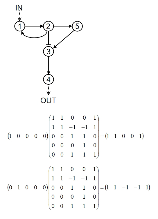
Arrows indicate excitatory signals, pistils inhibitory signals. All signals are being modeled here with the same strength (+1 for excitatory, -1 for inhibitory) for simplicity. When neuron 1 is stimulated the result is excitation of neuron 2 and 5 (and neuron 1 itself). The inhibitory signal from 2 to 3 will cancel the excitatory signal from 5 to 3 and no other node will be activated. Thus the first line of the matrix, representing the results of stimulating neuron 1 is: 1 1 0 0 1, with column 1 referring to node 1, column 2 to node 2, etc. the second row of the matrix represents the result of stimulating neuron 2: 1 1 -1 -1 1, note that nodes 3 and 4 are inhibited. Similarly for the other rows. Once we have constructed the matrix we can stimulate one or more nodes in the input matrix: illustrated is the stimulation of node 1 only and then node 2 only. Note this gives the expected output as we already computed manually in constructing the matrix. However, we are now free to see what happens when any number of nodes are stimulated, such as 1, 3 and 4: