Programming the Commodore 64
| | | | |
5 REM DALEK ANIMATION
7 POKE 53281,0 : POKE 53280,0
10 PRINT CHR$(147)
20 LET V = 53248
21 REM SET SPRITE COLORS
22 POKE V+39,2 : POKE V+40,2
23 POKE V+29,3 : POKE V+23,3
25 REM ENABLE SPRITES 0 AND 1
30 POKE V+21,3
35 REM POINTER FOR SPRITE DATA
49 REM DALEK LEFT-POINTING VIEW AT 13,15
50 FOR N=0 TO 62:READQ:POKE 832+N,Q:NEXT
52 FOR N=0 TO 62:READQ:POKE 960+N,Q:NEXT
55 REM DALEK REAR VIEW AT 128-129
57 FOR N=0 TO 62:READQ:POKE8192+N,Q:NEXT
59 FOR N=0 TO 62:READQ:POKE8256_N,Q:NEXT
60 REM DALEK FRONT VIEW AT 130-131
62 FOR N=0 TO 62:READQ:POKE8320+N,Q:NEXT
64 FOR N=0 TO 62:READQ:POKE8384+N,Q:NEXT
66 REM DALEK RIGHT-VIEW AT 132-133
67 FOR N=0 TO 62:READQ:POKE8448+N,Q:NEXT
68 FOR N=0 TO 62:READQ:POKE8512+N,Q:NEXT
70 POKE V+1,100: POKE V+3,100+21+21
75 GOSUB 1000
190 REM LEFT-POINTING VIEW TOP HALF
200 DATA 0,0,0,0,0,0,0,0,0,0,0,0,0,0,0
210 DATA 0,0,0,0,0,0,0,0,0,0,0,0
220 DATA 0,0,0,0,0,0,0,0,0,0,0,0
230 DATA 0,0,0,0,0,0,0,0,0,0,0,0
240 DATA 0,3,240,0,255,248,0,7,252
250 DATA 0,15,252
255 REM LEFT-POINTING VIEW BOTTOM HALF
260 DATA 0,4,136,0,15,252,0,4,136
270 DATA 0,15,252,128,26,170,255,250,170
280 DATA 128,58,170,1,255,254,0,21,84
290 DATA 0,10,170,0,21,84,0,42,170
300 DATA 0,21,84,0,42,170,0,85,84
310 DATA 0,42,170,0,85,84,0,170,170
320 DATA 0,85,84,1,255,255,1,255,255
330 REM REAR VIEW TOP HALF
340 DATA 0,0,0,0,0,0,0,0,0,0,0,0
350 DATA 0,0,0,0,0,0,0,0,0,0,0,0
360 DATA 0,0,0,0,0,0,0,0,0,0,0,0
370 DATA 0,0,0,0,0,0,0,0,0,0,0,0
380 DATA 0,129,0,0,126,0,0,255,0
390 DATA 1,255,128,1,255,128
400 REM REAR VIEW BOTTOM HALF
410 DATA 0,137,0,1,255,128,0,137,0
420 DATA 1,255,128,2,165,64,6,165,96
430 DATA 10,165,88,3,255,216,1,85,0
440 DATA 0,170,128,1,85,0,0,170,128
450 DATA 1,85,0,0,170,128,1,85,64
460 DATA 2,170,128,1,85,64,2,170,128
470 DATA 1,85,64,7,255,224,7,255,224
480 REM FRONT VIEW TOP HALF
490 DATA 0,0,0,0,0,0,0,0,0,0,0,0
500 DATA 0,0,0,0,0,0,0,0,0,0,0,0
510 DATA 0,0,0,0,0,0,0,0,0,0,0,0
520 DATA 0,0,0,0,0,0,0,0,0,0,0,0
530 DATA 0,129,0,0,126,0,0,231,0
540 DATA 1,231,128,1,255,128
550 REM FRONT VIEW BOTTOM HALF
560 DATA 0,165,0,1,255,128,0,165,0
570 DATA 25,255,128,26,165,80,7,255,224
580 DATA 3,255,192,3,255,192,1,85,0
590 DATA 0,170,128,1,85,0,0,170,128
600 DATA 1,85,0,0,170,128,1,85,64
610 DATA 2,170,128,1,85,64,2,170,128
620 DATA 1,85,64,7,255,224,7,255,224
630 REM RIGHT-FACING VIEW TOP HALF
640 DATA 0,0,0,0,0,0,0,0,0,0,0,0,0,0,0
650 DATA 0,0,0,0,0,0,0,0,0,0,0,0
660 DATA 0,0,0,0,0,0,0,0,0,0,0,0
670 DATA 0,0,0,0,0,0,0,0,0,0,0,0
680 DATA 15,192,0,31,255,0
690 DATA 63,224,0,63,240,0
700 REM RIGHT-FACING VIEW BOTTOM HALF
710 DATA 17,32,0,63,240,0,17,32,0
720 DATA 63,240,0,85,88,1,85,95,255
730 DATA 85,92,1,127,255,128,42,168,0
740 DATA 85,80,0,42,168,0,85,84,0
750 DATA 42,168,0,85,84,0,42,170,0
760 DATA 85,84,0,42,170,0,85,85,0
770 DATA 42,170,0,255,255,128
780 DATA 255,255,128
1000 POKE V+0,200:POKE V+2,200
1005 POKE 2040,13:POKE 2041,15
1010 FOR X = 200 TO 100 STEP-1
1020 POKE V+0,X: POKE V+2,X
1025 FOR P=1 to 10:NEXT
1030 NEXT X
1040 POKE 2040,130:POKE 2041,131
1050 FOR P = 1 TO 200:NEXT
1060 POKE 2040,132:POKE 2041,133
1070 FOR X = 100 TO 200
1080 POKE V+0,X: POKE V+2,X
1085 FOR P=1 to 10:NEXT
1090 NEXT X
1100 POKE 2040,128:POKE 2041,129
1120 GOTO 1000
Animating a Dalek Sprite
The Commodore 64, or C64, is a legacy 8-bit computer system popular in the 1980's. Along
with the Commodore Vic 20 and BBC Micro they were the first computers I learned to program.
With the appearance of a number of free C64 emulators for the PC I have returned to these
systems out of renewed curiosity. However, I have forgotten much of what I learned and I am
having to refresh my memory!
These old computers had no windows interface (although the BBC Micro did support windows
as a programming feature) instead everything is run from a 'command prompt' along with the
shortcut and function keys. However, they came with their own version of the BASIC
(Beginners All-purpose Symbolic Instruction Code) programming language. In computers like
the BBC Micro the BASIC was quite extensive, allowing easy control over many of the
computer's features (allowing me to write a fully-fledged database interface complete with
searching and editing tools in relatively little time, despite being in my mid-teens). Commodore
computers were often criticised for having somewhat incomplete BASIC and so being hard to
program. However, the Commodore BASIC had all one needed for most purposes, though like
many I also learned to program the C64 in machine-code (by writing code in assembly
language and then converting manually into machine-code with a look-up table and then using
BASIC DATA statements to read the code into the computer's memory).
Personally, I found the combination of BASIC and machine-code very satisfying. It also
encouraged the programmer to get to know the computer at silicon-roots level. Armed with a
C64 memory map there was very little one could not achieve by using POKE to add a value
into a memory slot, and PEEK to read the value in a memory slot. For example, POKE 53281,0
places the value 0 into memory location 53281, which is the register controlling screen color
and the value 0 turns the screen black. (Each memory location is one 8-bit byte and so can
hold a range of values from 0-255, though in this case there are only 16 color choices ranging
from 0 to 15).
Among the strengths of the C64 were its support for sprite graphics, with up to 8 sprites being
displayable at any one time (though changing the pointer for each sprite enables the shape of
the sprite to be instantly changed, allowing more sprite shapes in total) and also its sound
chip, which was probably the best on the market in its day. This combination made the C64 an
attractive computer for video games! As an example, we shall look at a program that creates
and displays an animated Dalek sprite.

Color Codes
0 BLACK
1 WHITE
2 RED
3 CYAN
4 PURPLE
5 GREEN
6 BLUE
7 YELLOW
8 ORANGE
9 BROWN
10 light RED
11 GRAY 1
12 GRAY 2
13 light GREEN
14 light BLUE
15 GRAY 3
0 BLACK
1 WHITE
2 RED
3 CYAN
4 PURPLE
5 GREEN
6 BLUE
7 YELLOW
8 ORANGE
9 BROWN
10 light RED
11 GRAY 1
12 GRAY 2
13 light GREEN
14 light BLUE
15 GRAY 3
Sprite Registers
Let V = 53248
Register Purpose
0 X-coord of sprite 0
1 Y-coord of sprite 0
2,3 (X,Y) of sprite 1
4,5 (X,Y) of sprite 2
6,7 (X,Y) of sprite 3
8,9 (X,Y) of sprite 4
10,11 (X,Y) of sprite 5
12,13 (X,Y) of sprite 6
14,15 (X,Y) of sprite 7
16 Most significant bit for X coord
21 Sprite enable: 1=appear, 0=disappear
29 Expand sprite in X-direction
23 Expand sprite in Y-direction
39-46 Sprite 0-7 color
Where register 0 is at memory location V+0 = 53248,
register 21 at V+21 = 53269, etc.
Line 7 sets the screen color (53281) and the screen border color (53280) - both to black in
this instance. The Dalek is made up of two sprites (sprites 0 and 1).
Line 10 clears the screen
Line 22 sets the color of the Dalek (sprites 0 and 1) - to red in this case
Line 23 doubles the size of sprites 0 and 1 (in both X and Y directions)
Line 30 enables sprites 0 and 1, so that they become visible
Lines 50-68 load the sprite data (contained at lines 190-780) into memory
Line 70 sets the Y-positions of the Dalek sprites
Line 75 branches to the animation subroutine beginning at line 1000
Lines 190-780 contain the data that makes up the Dalek shape
Lines 1000-1120 make-up the animation subroutine
Line 1000 sets the initial X-coordinates of sprites 0 and 1
Line 1005 sets the initial sprite 0 and 1 pointers to the data for a left-facing Dalek
Lines 1010-1030 move the Dalek to the left
Line 1040 sets the sprite 0 and 1 pointers to the forward-facing Dalek shape-data
Line 1050 causes the animation to pause whilst the Dalek turns to face viewer
Line 1060 sets the sprite 0 and 1 pointers to the data for the right-facing Dalek shape
Lines 1070-1090 move the Dalek to the right
Lines 1100 sets the sprite 0 and 1 pointers to the data for the rear-facing Dalek shape
Line 1120 causes the animation to loop as long as the program runs
Lines 1025,1050,1085 control the speed of the animation
The (default) sprite registers are as follows:
Register 21 controls which sprites are
displayed. Each of the 8 sprites is
allocated one binary digit in the 8-bit
byte, as follows:
Bit 128 64 32 16 8 4 2 1
Sprite 7 6 5 4 3 2 1 0
Such that to display only sprites 0 and
1 we set the value at register 21 to
(1+2 =) 3 like this: POKE V+21,3. To
switch off all sprites we would use:
POKE V+21,0.
Similarly we can switch on the sprite
expansions at registers 29 and 23,
thus to expand sprites 0 and 1 in both
directions (horizontal, X and vertical,
Y): POKE V+29,3 : POKE V+23,3. To
set the color of a sprite we use the
color table, so POKE V+39,2 sets
sprite 0 to red. [Multicolor ssprites are
supported, but these have lower
spatial resolution.]
Constructing Sprites
There always was software available for the C64 that allowed you to design sprites by filling in
grids and then the program calculates the byte values to enter into your DATA statements.
Failing that one can design them manually on graph paper, as I did for this Dalek all those
years ago.
There always was software available for the C64 that allowed you to design sprites by filling in
grids and then the program calculates the byte values to enter into your DATA statements.
Failing that one can design them manually on graph paper, as I did for this Dalek all those
years ago.
C64 Sprite Grid
(Click to view a blank sprite grid that you can use to draw your own sprites!)
Allocating the Sprite Data to Memory
Once we have all these values we need to read them into computer memory before the sprite
can be displayed. This is dealt with in lines 50-68 in the sample program, in which the READ
statement takes one value from the DATA list (lines 200 - 780) every time it executes,
advancing to the next data item each time (unless we use the instruction RESTORE which
resets the READ data pointer back to the beginning). Then each value is entered into memory
using POKE, for example, POKE 832,Q enters the value Q into memory location 832, which is
the start of the 13th memory block (13 x 64 = 832) where we enter the first value for one of the
sprites and consecutive values at 833, 834, etc. by using POKE 832+N,Q and advancing N by
one each time. N will start at zero and run to 62, since there are 63 bytes making up each sprite
(3 bytes per row x 21 rows = 63). This is achieved with:
FOR N=0 TO 62: READQ: POKE 832+N,Q: NEXT
at line 50. The memory beginning at 832 for the first sprite data and 960 for the second (line
52) puts this data into the cassette (tape I/O) buffer (828-1019). [See a C64 memory map.]
This is convenient as we are not needing this buffer at present, but only a couple of sprites'
data will fit in there so the rest are added to memory starting at 8192. The program gets stored
in RAM between 2048 and 40959, so we are eating into this space. For all but the largest
programs this is fine, and since the program storage begins at location 2048 it is better to put
the sprite data further along. We are not at liberty to use any available RAM for the sprites,
since we have to set the sprite pointers so that the computer knows where to find the data for
each. The sprite pointers are stored at registers 2040 (sprite 0) to 2047 (sprite 7) and we set
them in line 1005, for example:
POKE 2040,13:POKE 2041,15
This sets the pointer for sprite 0 (the head of the Dalek) to memory block 13, i.e. location 13 x
64 = 832. This points to the start of the sprite data which continues to 832 + 62. The pointer for
sprite 1, the Dalek body, is set to memory block 15 (memory location: 15 x 64 = 960). This is
where we put the data for the lefty-facing Dalek, so now sprites 0 and 1 create a left-facing
Dalek! By changing the pointers we animate the sprites, causing the Dalek to appear to turn,
as it changes from left-facing to front-facing, for example. We do this in line 1040:
POKE 2040,130:POKE 2041,131
Turning the pointers to the 130th and 131st memory blocks, that is locations (130 x 64) 8320
and (131 x 64) 8384, which is indeed where we poked the data for the front-facing Dalek in
lines 62 and 64.
Since each memory register can only hold one byte, the highest memory location a sprite
pointer can point to is the 255th block, that is location 255 x 64 = 16 320. Unfortunately, this
may interfere with a long program stored at this location!
Sprite Collision Detection
In a computer game we clearly need to know if a sprite collides with a background object, such
as a wall, or another sprite, such as a missile. The C64 handles this elegantly. The memory
location or register at 53278 records sprite to sprite collisions, whilst the register at 53279
detects sprite-data collisions (i.e. sprite-background graphics collisions). The byte stored in
these addresses represents each of the 8 possible sprites by one bit. If there is a collision then
the corresponding bit(s) of the colliding sprite(s) is(are) switched on. We use PEEK to read the
value, e.g. C = PEEK 53278. If there has been a collision between sprite 7 and 2, for example,
then the value of C would be 132 ( = 128 + 4). Every time we peek the values in these registers
they are automatically cleared, i.e. set to zero, so we can read the value at intervals to
determine what has collided since we last checked.
The V+16 Register
Another important register is the register at memory location V+16 (53248 + 16 = 53264). This
determines the most significant bit of the sprite's horizontal position or X-coordinate. Consider
register V+0, which stores the X-coordinate of sprite 0. We can set this position to any value
from 0, at the very left edge of the screen, to 255, near to the right of the screen, but not quite!
The default screen is 320 pixels wide. How then do we position a sprite at X-values between
256 and 320? If we set the sprites corresponding bit at V+16, its most-significant bit, then this
tells the computer to set its X-position between 256 and 320. For example, for sprite 3, whose
bit is the bit with value 8, we would use: POKE V+16,8. Now if we set the X-coordinate to zero,
POKE V+6,0 sprite 3 is positioned at X = 256! If we set it's X-value to 63, POKE V+6,63 then it
is moved to X = 319. To move it back to X less than 255, we turn off its most-significant bit at
register V+16.
Inhabitants of the Planet Skaro
Skaro, homeworld of the Daleks, was home to a number of bizarre life-forms, including animals
apparently made of living metal. Many of these life-forms were annihilated in a nuclear war
which petrified much of the planet's forests and turned vast swathes of it into desert wasteland.
However, some of the surviving inhabitants underwent rapid evolution, and some, possibly once
humanoid, evolving into crawling green blobs. Indeed, the developing Daleks were nourished
on similar aggressive green blobs which they themselves had to catch and kill, in a process
designed to select Daleks for aggression. At one point in their evolution, the Daleks became
green blobs themselves before reverting to a tentacled stage. Thus, no Skaro-scape would be
complete without crawling green blobs! The code below generates and animates such a blob,
using a multicolor sprite.
Each sprite consists of a grid of pixels, 24 columns by
23 rows. The Dalek sprite is actually two sprites
moved together as one. The head dome makes up
one sprite, allowing the head to be turned whilst the
body remains stationary, for example, or for the head
to be blown off! The rest of the Dalek body is the
second sprite.
Pixels that are switched on assume the color of the
sprite, those that are switched off are transparent and
assume whatever is in the background.
Sprites have a set priority, or z-depth, determining the
order they assume when passing over one-another.
By default, sprite 0 will pass in front of sprite 1,
whenever the two sprites overlap on the screen.
Sprite 1 will pass in front of sprite 2, etc. Thus the
lower number sprite has the higher priority and will
appear in front of a higher number sprite. Remember,
only sprite numbers 0-7 are possible.
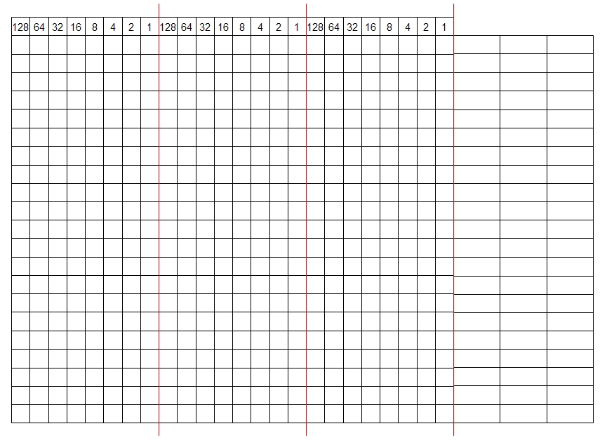
Sprite data consists of a series of bytes. A byte is a
set of 8 bits, each bit representing one pixel, so our
24 columns can be represented by three bytes per
row.
To see how this works, consider the example of the
bottom 5 rows of the left-side head sprite (the other
upper 16 rows have all pixels set to zero). To switch
on a pixel we set its corresponding bit value to 1, and
set it to zero to switch it off.
23 rows. The Dalek sprite is actually two sprites
moved together as one. The head dome makes up
one sprite, allowing the head to be turned whilst the
body remains stationary, for example, or for the head
to be blown off! The rest of the Dalek body is the
second sprite.
Pixels that are switched on assume the color of the
sprite, those that are switched off are transparent and
assume whatever is in the background.
Sprites have a set priority, or z-depth, determining the
order they assume when passing over one-another.
By default, sprite 0 will pass in front of sprite 1,
whenever the two sprites overlap on the screen.
Sprite 1 will pass in front of sprite 2, etc. Thus the
lower number sprite has the higher priority and will
appear in front of a higher number sprite. Remember,
only sprite numbers 0-7 are possible.
Sprite data consists of a series of bytes. A byte is a
set of 8 bits, each bit representing one pixel, so our
24 columns can be represented by three bytes per
row.
To see how this works, consider the example of the
bottom 5 rows of the left-side head sprite (the other
upper 16 rows have all pixels set to zero). To switch
on a pixel we set its corresponding bit value to 1, and
set it to zero to switch it off.
For each byte the bits are numbered from right to left, and since we are dealing with binary they
are powers of 2. A byte value of 255 turns all 8 bits in the byte on, a value of zero turns them all
off. For example, looking at the third row, the three byte values for that row are 0, 255 (128 +
64 + 32 +16 + 8 + 4 + 2 + 1) and 248 (128 + 64 + 32 + 16). This is how the DATA values
making up the Dalek shapes were obtained.
Good References For Programming the C64
Coming soon:
Multicolor Sprites
Background Graphics
Sound on the C64
Programming machine code on the C64
Inverting bytes in sprites
Coming soon:
Multicolor Sprites
Background Graphics
Sound on the C64
Programming machine code on the C64
Inverting bytes in sprites
10 PRINT CHR$(147)
20 V=53248
30 POKE V+21,1
40 FOR N=0 TO 62: READQ: POKE 832+N,Q: NEXT
50 FOR N=0 TO 62: READQ: POKE 960+N,Q: NEXT
55 REM MC SPRITE MODE ON
60 POKE 53276,PEEK(53276) OR 1
65 REM SET SPRITE COLORS
70 POKE V+39,5: POKE 53285,13: POKE 53286,5
80 GOSUB 1000
200 DATA 0,0,0,0,0,0,0,0,0,0,0,0
210 DATA 0,0,0,0,0,0,0,0,0,0,0,0
220 DATA 0,0,0,0,0,0,0,0,0,0,0,0
230 DATA 1,188,0,7,255,0,21,103,0,21,87,128
240 DATA 21,171,192,7,170,224,1,255,248
250 DATA 0,57,255,0,0,0
260 DATA 0,0,0,0,0,0,0,0,0,0,0,0,0,0,0
270 DATA 0,0,0,0,0,0,0,0,0,0,0,0,0,0,0
280 DATA 0,31,128,0,123,208,0,213,96
290 DATA 0,213,96,0,213,192,0,106,192
300 DATA 0,61,192,0,61,112,0,15,240
310 DATA 0,15,252,0,0,0
1000 I=200
1002 POKE V+1,100
1005 POKE 2040,13
1010 FOR X=1 TO 10: POKE V+0,I-X: I=I-1
1012 NEXT X
1015 FOR P=1 TO 100: NEXT P
1020 POKE 2040,15
1030 FOR P=1 TO 100: NEXT P
1040 IF I<=10 THEN STOP
1050 GOTO 1005
Comment on this article!